
|
||||||||||||||||||||||||||||||||||
|
eMuCo News
3rd Issue - November 2009 |
||||||||||||||||||||||||||||||||||
|
||||||||||||||||||||||||||||||||||
| By: Emil Matus emil.matus@ifn.et.tu-dresden.de Oliver Arnold oliver.arnold@ifn.et.tu-dresden.de Technische Universität Dresden |
Embedded multi-core technology increases the overall system performance by providing environment enabling parallel execution of multi-threaded software. However, the resulting performance is still not adequate in many applications and hence an acceleration using additional processing elements (PEs) is necessary. A lot of challenges arise in this context as e.g. the scalability and efficiency of acceleration, generality of solution, flexibility, run-time management and use of processing elements, programming interface and the integration within the eMuCo software environment. |
Motivation of this work is to develop the concept of scalable acceleration subsystem based on heterogeneous processing elements and unified programming interface. In addition to this, the motivation is to decouple the problem of software development and the use of processing elements by providing run-time management unit called CoreManager dedicated to mapping program parts being subject of acceleration to PEs. The principle of the acceleration subsystem is depicted in Fig.1. |
|
| Figure 1: Principle of scalable acceleration subsystem | |
 |
|
|
|
|
| Figure 2: Principle of programming interface | |
 |
|
|
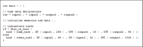
In general, the CoreManager implements a dynamic scheduling strategy considering instantaneous PEs configuration which enables performance scalability by adding or removing PEs without the need of software modifications. This allows for easy system adaption to new demands. Based on the input and output data blocks, dependency checking against all previously queued tasks is performed and annotated in the CoreManager. Figure 3 shows an example of two tasks. Task 2 depends on partial output information of Task 1. Thus, Task 2 has to be delayed until the completion of Task 1. As soon as all dependencies for a certain task are resolved and an appropriate processing element is available, this task is started. Before task execution, program and input memories are copied from the global to the local PE memory. After task completion, the local PE memory is copied back to the global memory. |
|
| Figure 3: Task dependencies | |
 |
The integration of the CoreManager can be done in different ways. One possibility is the integration in the microkernel which would reduce the communication overhead to a minimum due to a shared second level cache within the environment. Another option for the integration would be to implement it to a separate processor outside the scope of the microkernel. In this case the CoreManager would run in parallel to the main processors and the speed degradation would be minimized. |
| Figure 4: CoreManager Integration | |
 |
The integration of the CoreManager is done as an L4 Server. Thus, the CoreManager is a user program running on top of the L4 Microkernel and acts as a devices driver for the VMs. Communication to other VMs is done in two ways. First, shared memory is used. Thus, both communication partners have the same physical memory mapped in their virtual address space. Second, virtual interrupts are used to inform the corresponding VM about new events, e.g. the finishing of a task or the availability of new tasks in the other direction of communication. The IO-Manager within the L4 System is responsible for device resource management according to the given IO-configuration. E.g. different device interrupts have to be made available for specific clients, such as the corresponding L4 Server or virtual machine. In this case the CoreManager will receive all these interrupts. Now, virtual interrupts are used to inform the correct VM about finishing its tasks. |
| back to eMuCo News | |

ICT - Embedded Multicore processing for Mobile Communications
Questions? Comments? Email us at: info@eMuCo-News